Universal signal converter WZ109REG21
converts signals from V, mA, potentiometer, PT100, PT1000, PT500, Ni100, KTY81/84, NTC and thermocouples into a standard current or voltage signal,
3-way galvanic isolation
- For current and voltage signals, potentiometers, Pt100, Pt1000, Pt500, Ni100, KTY81/84, NTC and thermocouples type J, K, R, S, T, E, B and N.
- Galvanic 3-way isolation, test voltage 1.5 kV (50 Hz, 1 minute)
- Converts the input signals into a 0/4 - 20 mA, 0/2 - 10 V or 0/1 - 5 V signal
- Supply via 10 - 40 VDC, 19 - 28 VAC
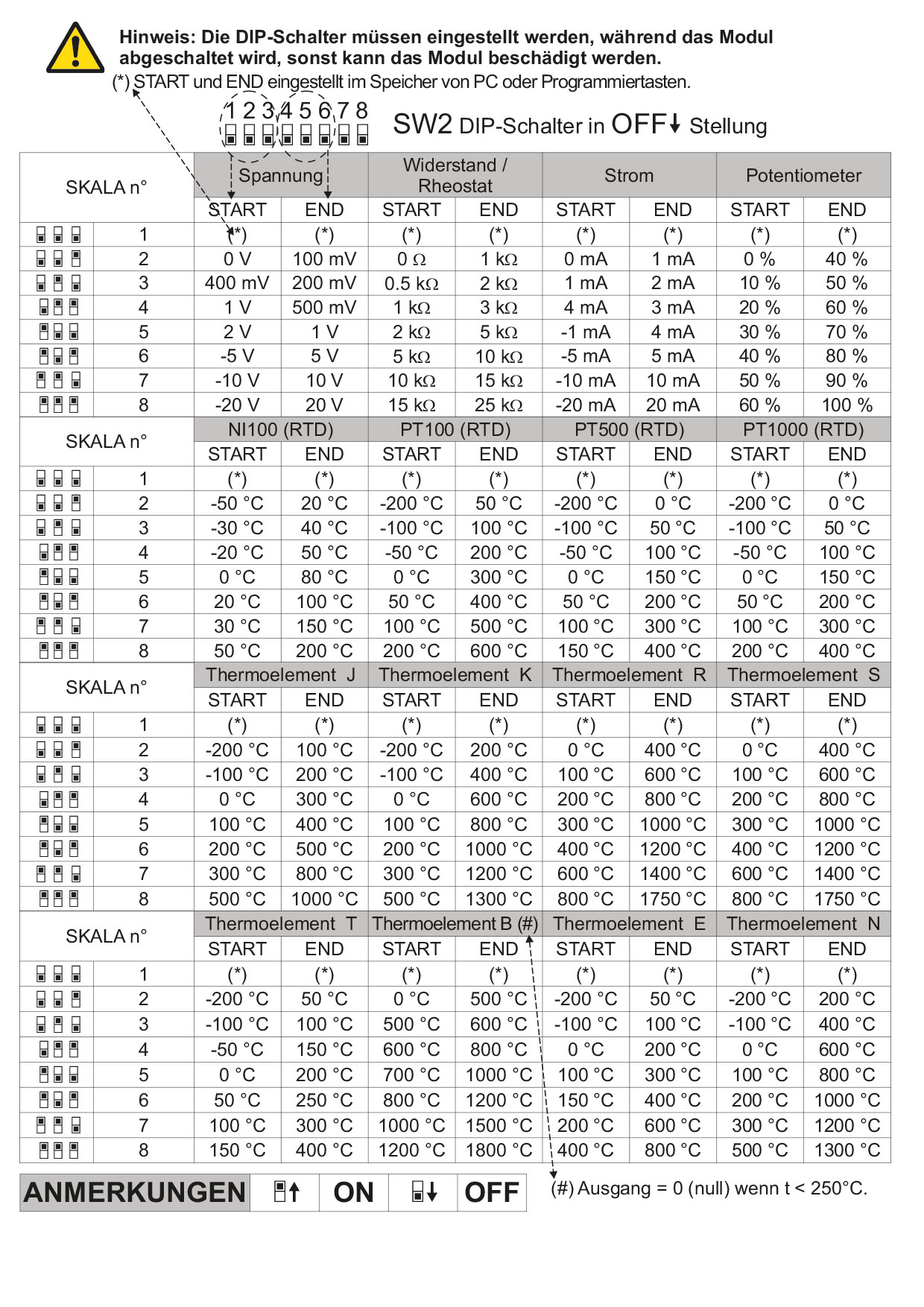
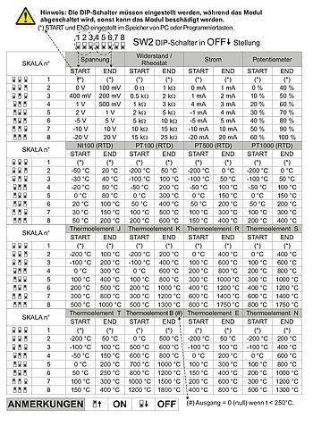
- Simple commissioning possible via DIP switch or USB interface
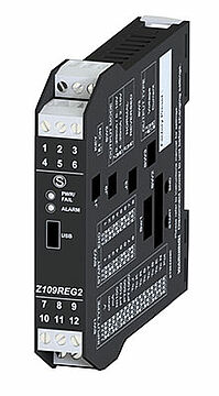
The WZ109REG21 universal signal converter converts current/voltage signals, signals from temperature sensors as well as resistance signals and potentiometer signals into a standard current or voltage signal. The output signal is linearly proportional to the input. The additional input/output can be used to output an alarm value or to operate several WZ109REG21s in multiplex mode on a PLC. The device is fully set via DIP switches, software on the PC or via the TEST3 calibration device and is immediately ready for operation. For mounting, the WZ109REG21 is simply snapped onto a DIN rail.
Entrance:
Voltage: Two-pole from 75 mV up to 20 V in 9 scales, input impedance 1 MOhm, max. resolution 15 bit + sign
Current: Two-pole up to 20 mA, input impedance ~50, resolution: 1 µA.
Thermal resistance (RTD) PT100, PT500, PT1000, NI100, KTY81, KTY84-130/-150, NTC: Measurement with 2, 3 or 4 wires, excitation current 0.56 mA, resolution 0.1 °C, automatic detection of cable interruption or RTD interruption. For NTC resistance value < 25 kW KTY81, KTY84 and NTC only adjustable via software.
Thermocouple (TC): Type S, T, J, N, K, E, R, B. Resolution 2.5 μV, automatic detection of cable interruption or TC interruption, input impedance > 5 MOhm.
Rheostat: end scale min. 500 Ohm, max. 25 kOhm.
Potentiometer: Excitation voltage 300 mV, input impedance > 5 MOhm, potentiometer value from 500 Ohm to 100 kOhm (using a 500 Ohm resistor connected in parallel).
Sampling frequency:
Variable from 240 PLC with 11 bit resolution + sign to 15 PLC with 15 bit + sign resolution (typical values).
Response time:
35 ms with 11-bit resolution, 140 ms with 16-bit resolution (measurement of voltage, current, potentiometer).
Output:
Voltage range: 0-5 V / 0-10 V / 1-5 V / 2-10 V, min. load resistance 2 kOhm
Current range: 0-20 / 4-20 mA, load resistance 600 Ohm
Resolution: 2.5 A/ 1.25 mV
Data storage:
EEPROM for all configuration data; storage time 40 years
Alarm output/strobe input
1 relay output as NC contact, 1 A @ 30 VDC/AC,
can alternatively be used as strobe input with contact input.
Burden
V > 2 KOhm, A < 600 Ohm
Resolution
11 to 15 bits depending on the setting
Accuracy
between +/- 0.1 % and +/- 0.5 % depending on the range
Linearity
0.02 % to 0.1 % depending on the setting
Temperature coefficient
0,01 % / °K
Response time
35 ms
Setting
DIP switch or via the setup software
Scaling
Linear, square root determination
Filter
Switchable filter
Error signaling
LED, fault / settings
Assembly
35 mm DIN rail
Ambient conditions
Working temperature: -10 to +60 °C
Storage temperature: -20 to +85 °C
Humidity: 30 to 90 % non-condensing
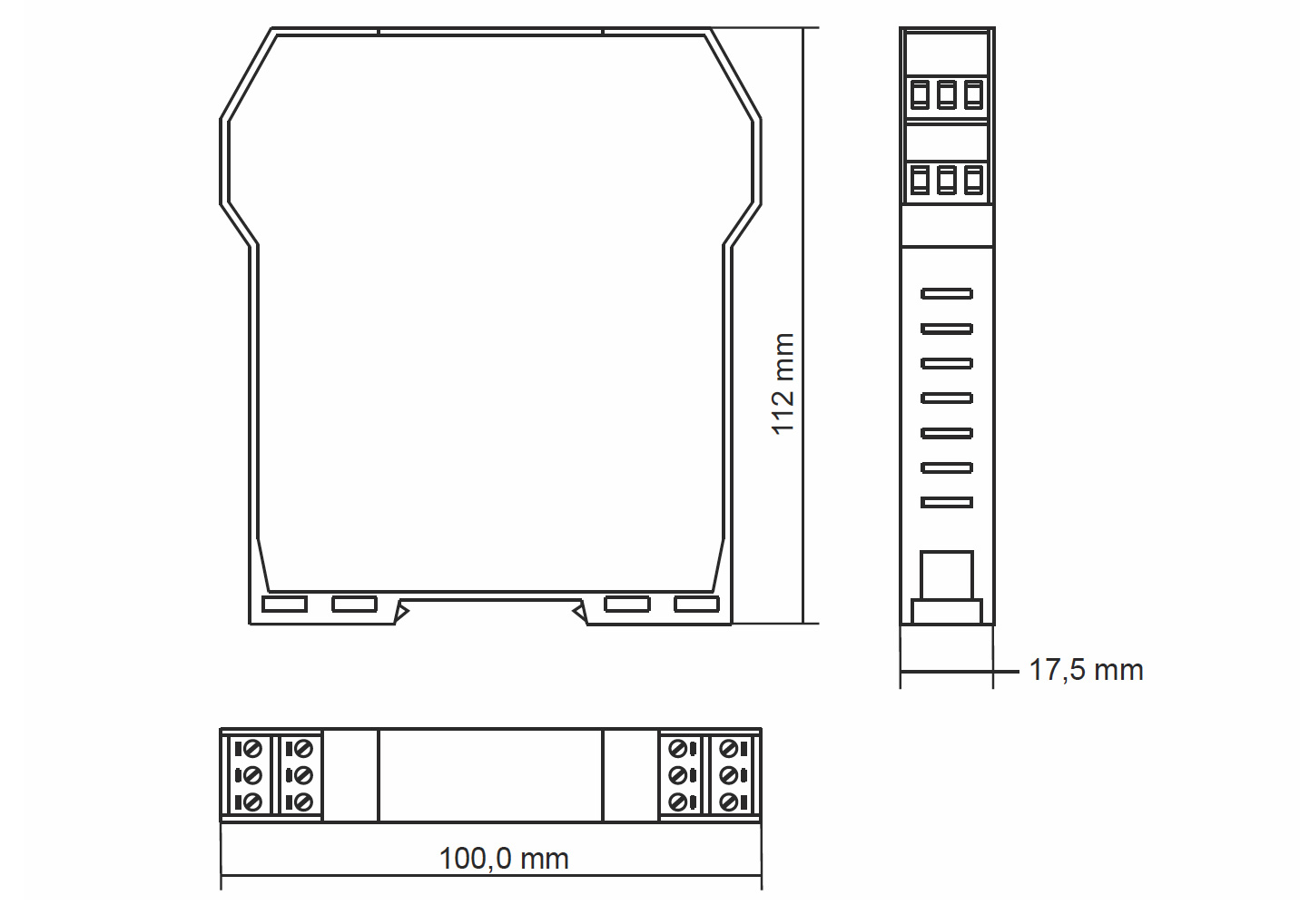
Dimensions(W x H x D)
17.5 mm x 115 mm x 130 mm
Manufacturer:
Seneca s.r.l.

You can download the handout Signal converter here.
 Download (2.41 MB)


Configuration software for signal converters.
By downloading and using software and apps from this website, I agree to the GTC and the supplementary software clause.

 to top
 Contact
 Request form