Signal converter for thermocouples WK109TC
converts signals from a thermocouple temperature sensor into a V or mA standard signal,
3-way galvanic isolation
- NEW: 6 mm housing
- Converts a signal from a thermocouple into a 0/4-20 mA, 20-0/4 mA, 0-10 VDC, 10-0 VDC or 0/1- 5 VDC standard signal
- 14 bit resolution
- Adjustable alarm threshold
- Supply via input terminals or K-bus rail
- Operating voltage 19.2 VDC to 30 VDC, max. 25 mA
- Simple commissioning via DIP switch
- Galvanic 3-way isolation, test voltage 1.5 kV (50 Hz, 1 minute)
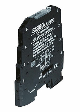
The WK109TC0 signal converter converts signals from a thermocouple temperature sensor into a V or mA standard signal. The output signal is linearly proportional to the input. The device is fully set via DIP switches and is immediately ready for operation. The WK109TC0 is simply snapped onto a DIN rail for installation.
Channels
1 input:
Thermocouple type S, T, J, N, K, E, R, B according to IST standard.
The impedance is 10 MOhm. The ranges can be set in steps using DIP switches; the minimum temperature range is 100 °C.
Cold junction via internal sensor,
Accuracy 1.5 °C
1 output:
Voltage range: 0 to 10, 10 to 0, 0/1 to 5, 5 to 1/0 VDC,
Current range: 0/4 to 20, 20 to 0/4 mA
Alarm output: SSR, 24 VDC/AC, 60 mA
adjustable via DIP switch.
The output signal is linearly proportional to the input.
Alarm output:
Static relay, nominal voltage 24 VDC/AC, current 60 mA, overvoltage protection 50 volts, adjustable threshold value with hysteresis.
Burden
V ≥ 2 KOhm, A ≤ 500 Ohm
Resolution
14 bit, 1 mV, 2 μA D /A converter
Accuracy
0.1% of the range. 14 bit resolution
Temperature coefficient
< 120 ppm / K
Short-circuit resistance:
1,500 VAC between input, supply and output in all directions.
Safety:
EN61010-1:2013-10
EMC:
EN61000-6-2:2006-10
EN61000-4-4:2013-01
EN61000-6-4:2007-11 + A1:2013-01
EN61000-4-5:2015-05
EN61000-4-2:2011-04
EN61000-4-6:2014-09
EN61000-4-3:2007-04 + A1:2009-01 + A2:2011-01
EN61000-4-11:2006-02
Response time
< 40 ms (without filter)
< 40 / 88 ms (with filter)
Scaling
Linear
Filter
Switchable filter
Error signaling
0 mA to 20 mA output: I = 0 mA or ≥ 21 mA
4 mA to 20 mA Output: I = ≤ 3.5 mA or ≥ 21 mA
0 V to 10 V or 0 V to 5 V Output: I = 0 V or ≥ 10.5 V or ≥ 5.25 V
1 V to 10 V or 1 V to 5 V output: I = ≤ 0.75 V or ≥ 10.5 V or ≥ 5.25 V
Display
LED:
Fault / alarm / limit value / output status of the relay
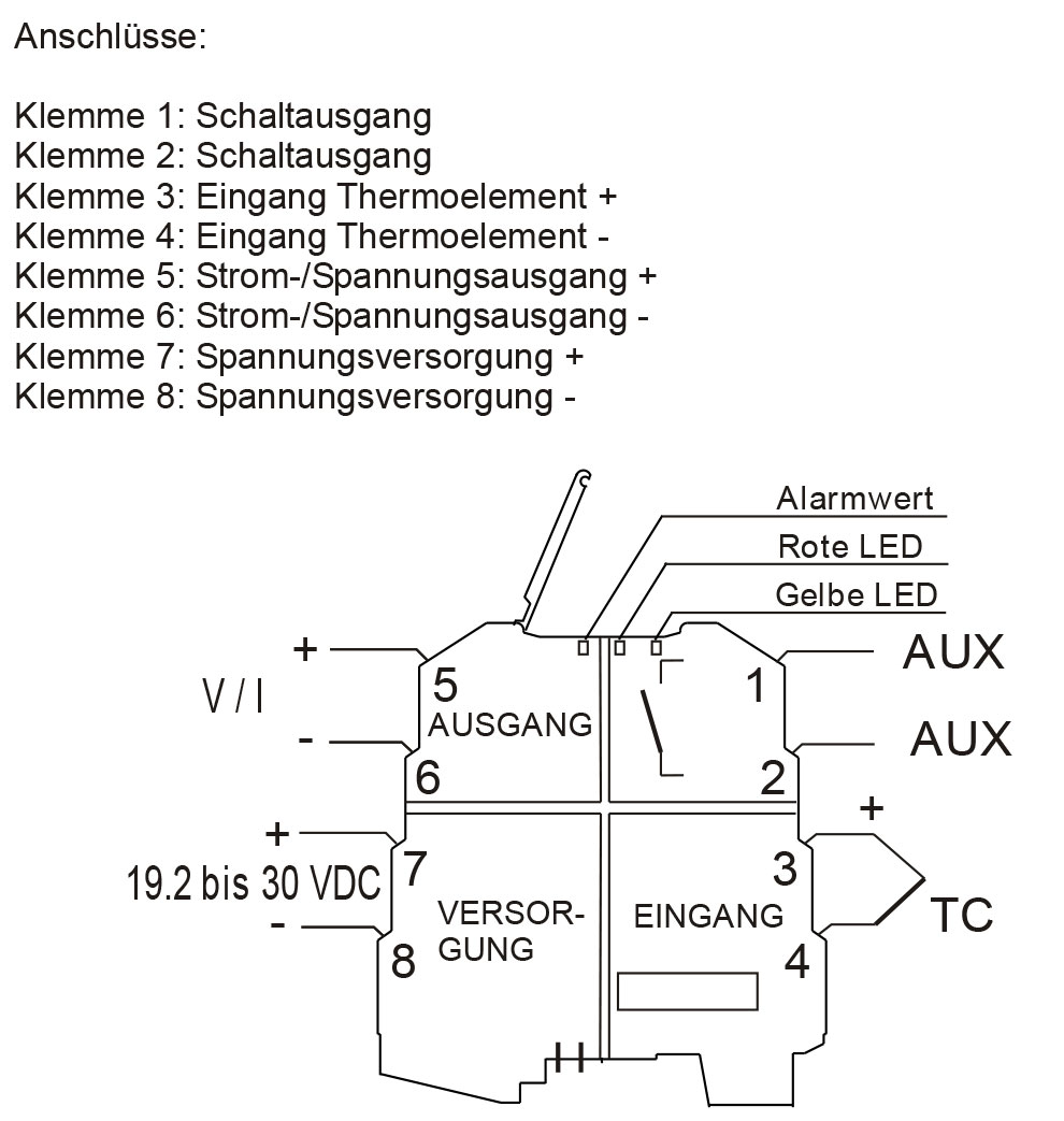
Supply:
19.2 VDC to 30 VDC, max. 21 mA at 24 VDC.
Power is supplied via the terminals or via the K-bus.
Assembly
35 mm DIN rail, WK bus interface
Ambient conditions
Working temperature: -20 °C to +65 °C,
Storage temperature: -40 °C to +85 °C,
Humidity: 30 % to 90 % non-condensing at 40°C
Short-circuit resistance:
1,500 VAC between input, supply and output in all directions.
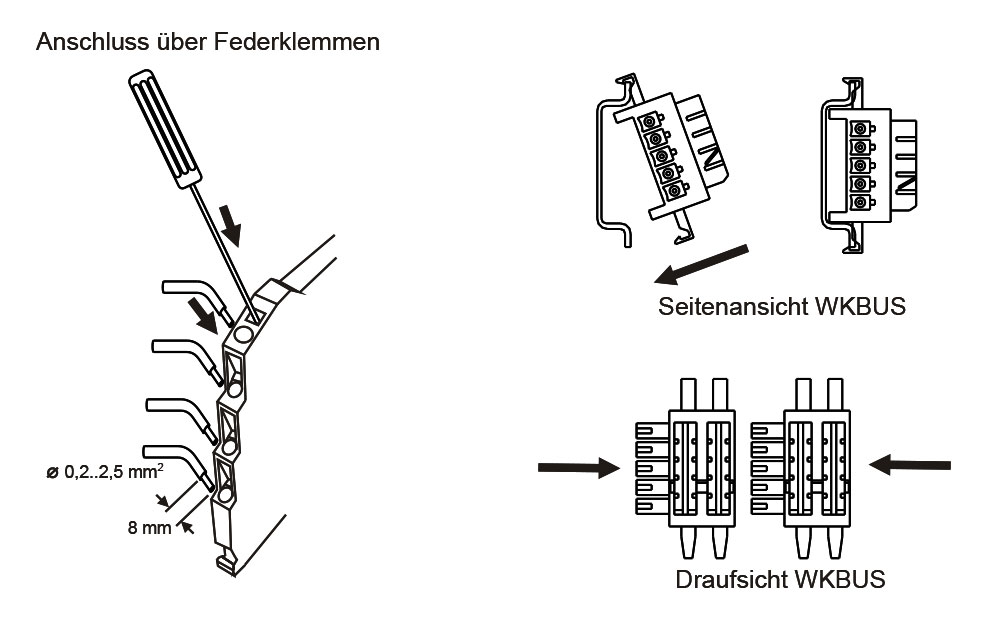
Connection:
Spring terminals from 0.2 to 2.5 mm²
Protection class:
IP20
Housing:
Sturdy plastic housing.
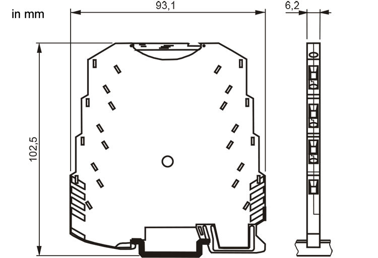
Dimensions (W x H x D)
6.2 mm x 93.1 mm x 102.5 mm
Weight
approx. 50 g
Scope of delivery:
Device, operating instructions
Manufacturer:
Seneca s.r.l. Italy


You can download the handout Signal converter here.

