Graphic display PM-50 with digital input
2-fold counter/tachometer with mathematical function
3.5" or 4.3" 18-bit color display with resistive touchscreen and swipe gesture
WiFi 4 connectivity (ModbusTCP communication)
- 3.5" or 4.3" 18-bit color display with resistive touchscreen
- 2-fold counter/tachometer with mathematical function
- Slave display
- WiFi 4 connectivity (ModbusTCP communication)
- Universal input for digital signals
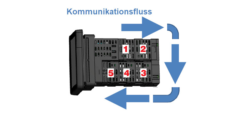
- Modular extensions possible


The new PM-50 graphic display with its universal digital input can be used with almost all commercially available NPN, PNP sensors, CMOS, TTL, potential-free contacts, permanent magnet sensors, as well as programming, operating and control technologies for many applications. The display can be used as a simple counter or tachometer. The mathematical functions, such as addition and subtraction, allow you to offset the counters/tachometers against each other and display them as counter C or tachometer C on the display. It is available with a 3.5" or 4.3" 18-bit (TFT) color display with resistive touchscreen and allows the user to easily switch between relevant screens by "swiping" to obtain comprehensive operating data for monitoring systems and products. Visual warnings and alarms are shown on the display, but can also be viewed on mobile devices via the PM-50 app. The app is available in the Apple and Google Play Store. A program wizard on the device makes it easy to set up the PM-50, but alternatively the display can also be programmed via the app or a web browser. For remote access to important workflows and process data, the display has an RS485 interface for Modbus RTU communication; Modbus TCP communication takes place via WiFi (4th gen.). Thanks to the possibility of simple modular expansion of the display on site, an RS232 interface for Modbus, an Ethernet connection (RJ45) and an analog output and / or relay output module (2x changeover contacts or 4x NO contacts) can be implemented quickly.
Entrance areas:
Software configurable input types:
NPN, PNP sensors, CMOS, TTL, dry contacts, permanent magnet sensors
Inputs support NPN or PNP logic with configurable input filtering for low frequency signals or switching contact debounce. Not isolated from common sensor input
Logic: Input trigger level VIL = 1.2 V max.;VIH = 3.75 V min.
NPN: Internal 7.8 KΩ pull-up resistor to +5 VDC, 0.7 mA max.
PNP: Internal 3.9 KΩ pull-down resistor; 7.3 mA max. @ 28 VDC, VMAX = 30 VDC
Magnetic pickup: VIN_PK = 200 mV; VIN_HSYS = 100 mV; must also have PNP selection enabled by software. VMAX = ± 40VPEAK or 28 Vrms
Phase discriminator:
If any double counting mode is used, user inputs 1 and/or 2 will accept the second signal of each signal pair. The user inputs do not have the software selection options Logic/Mag, HI/LO Freq and NPN/PNP. The user inputs are a logic input for which no low-frequency filtering is implemented in the software.
The user input can only be selected as NPN/PNP via the User input active parameter.
Display:
Counter:
9-digit
Display range: -99,999,999 to 999,999,999
Indicators: Cnt-A, Cnt-B, Cnt-C
Max. Input frequency:
When setpoints are disabled 35 KHz for all modes except phase discriminator (quad x4) 32 KHz
If the setpoints are activated 20 KHz for each mode except
Phase discriminator (quad x1) 19 KHz
Phase discriminator (quad x2) 17 KHz
Phase discriminator (quad x4) 10 KHz
Tachometer:
6-digit
Minimum input frequency: 0.001 Hz
Maximum input frequency: 50 KHz
Accuracy: ± 0.01%
Display update time from 0.1 to 999.9 seconds
Display:
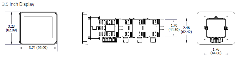
4.3" or 3.5" color TFT display with analog resistive touchscreen
3.5" display:
Colors: 262,144 K
Pixels: 320 x 240
Brightness: 540 cd/m²
LED backlight service life: 30,000h*
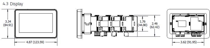
4.3" display:
Colors: 262,144 K
Pixels: 480 x 272
Brightness: 420 cd/m²
LED backlight service life: 30,000h*
*at room temperature (25 °C)
User inputs:
Two programmable user inputs
Max. Input voltage: 30 VDC
NPN (LO):
Active: VIN < 0.9 VDC
Inactive: VIN > 2.4 VDC
20 KOhm pull-up at 3.3 V
PNP (HI):
Active: VIN > 2.4 VDC
Inactive: VIN < 0.9 VDC
20 KOhm pull-down
SSR outputs (OnBoard):
2 outputs, only NPN or PNP mode synchronous, not separately adjustable.
NPN mode (sink):
Type: Switched DC, N-channel open-drain MOSFET
Max: 100 mA
VDS ON: 0.3 V @ 100 mA
VDS MAX: 30 VDC
Current consumption in standby: 0.5 mA max.
PNP mode (source):
Type: Switched DC, P-channel open-source MOSFET
Max: 100 mA
VDS ON: 0.3 V @ 100 mA
VDS MAX: 30 VDC
Current consumption in standby: 0.5 mA max.
Sensor supply:
24 VDC, ±5%; @max. 50 mA
RS485 interface (OnBoard):
Uses the Modbus RTU protocol (RS485)
Baud rate: Up to 115,200 bit/s
Data format: 7 or 8 bit; odd, even or no parity; 1 or 2 stop bits
Isolation: 500 Vrms to sensor, user and digital inputs.
Not isolated to semiconductor outputs
Power supply:
10 VDC to 30 VDC; 4.6 W (without modules)
Max. Power consumption: 12 W (with modules)
Isolation: 500 Vrms for 1 min. to all inputs and outputs.
WiFi 4:
Output power up to 20.5 dBm
Frequency: 2412 MHz to 2484 MHz
Channels: 1 to 13
Note: Channel/frequency limitation is based on the configured country/region code.
Wi-Fi compliance:
TCP/IP; 802.11 b/g/n
Modbus TCP communication via WiFi 4 possible.
Memory:
Non-volatile memory, retains all programmable parameters and display values
Memory card: microSD cards up to 32 GB in FAT16/FAT32 format possible.
Ambient conditions:
Operating temperature range: -10 °C to +55 °C
Storage temperature range: -20 °C to +60 °C
Humidity during operation and storage: 0 % to 85 % rH, non-condensing
Altitude: Up to 2000 meters
Vibration and shock:
Vibration: 5-500 Hz, 2 g
Shock: 20 g (10 g relay)
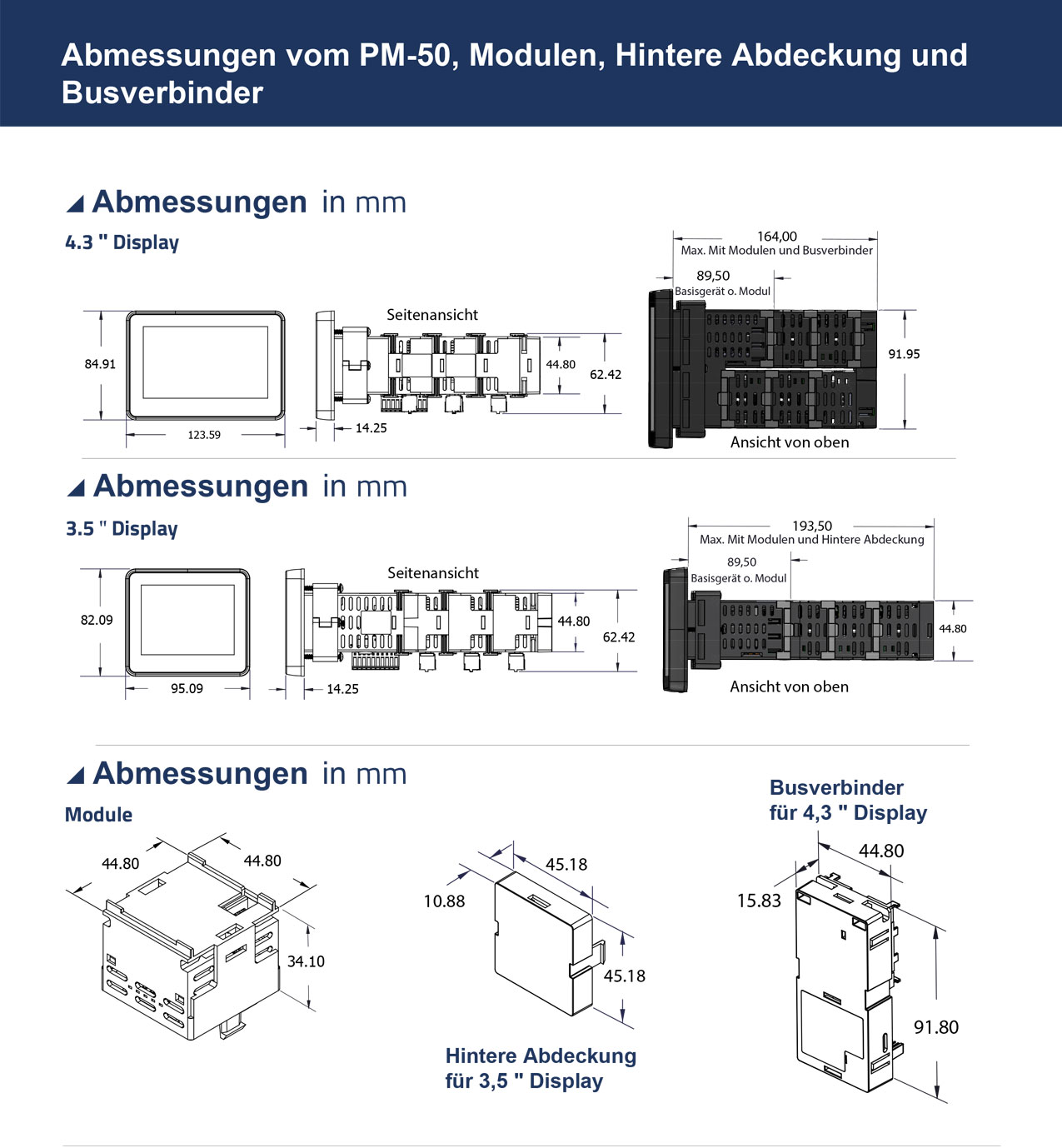
Dimensions (WxHxD):
PM500D0301600F00:
Installation dimensions (WxHxD): 44.8 mm x 44.8 mm x 87.17 mm
Height without terminal strips
Depth specification corresponds to basic device incl. rear cover
Installation depth with max. number of modules: 189.47 mm
Panel cut-out: DIN 45 x 45
Display/front (WxHxD): 95.09 mm x 82.09 mm x 14.25 mm
Rear cover (B): 11 mm
PM500D0400800F00:
Installation dimensions (WxHxD): 91.95 mm x 44.8 mm x 92.20 mm
Height without terminal strips
Depth specification corresponds to basic device incl. bus connector for PM-50 4.3"
Installation depth with max. number of modules: 160.40 mm
Panel cut-out: DIN 92 x 45
Display/front (WxHxD): 123.59 mm x 84.91 mm x 14.25 mm
Bus connector rear cover (B): 15 mm
Max. Sheet thickness: 6.35 mm
Min. sheet thickness for NEMA 4X/IP65 requirements: 1.02 mm
Housing:
One-piece cover/housing.
Flame retardant.
Installation seal and installation fastening included
Weight:
3.5" device: approx. 230 g
4.3": device approx. 326 g
Protection class:
Type 4X for indoor use only
IP65 (front)
IP20 (rear)
Certificates:
CE, UKCA, FCC, UL,
Scope of delivery:
PM500D0301600F00:
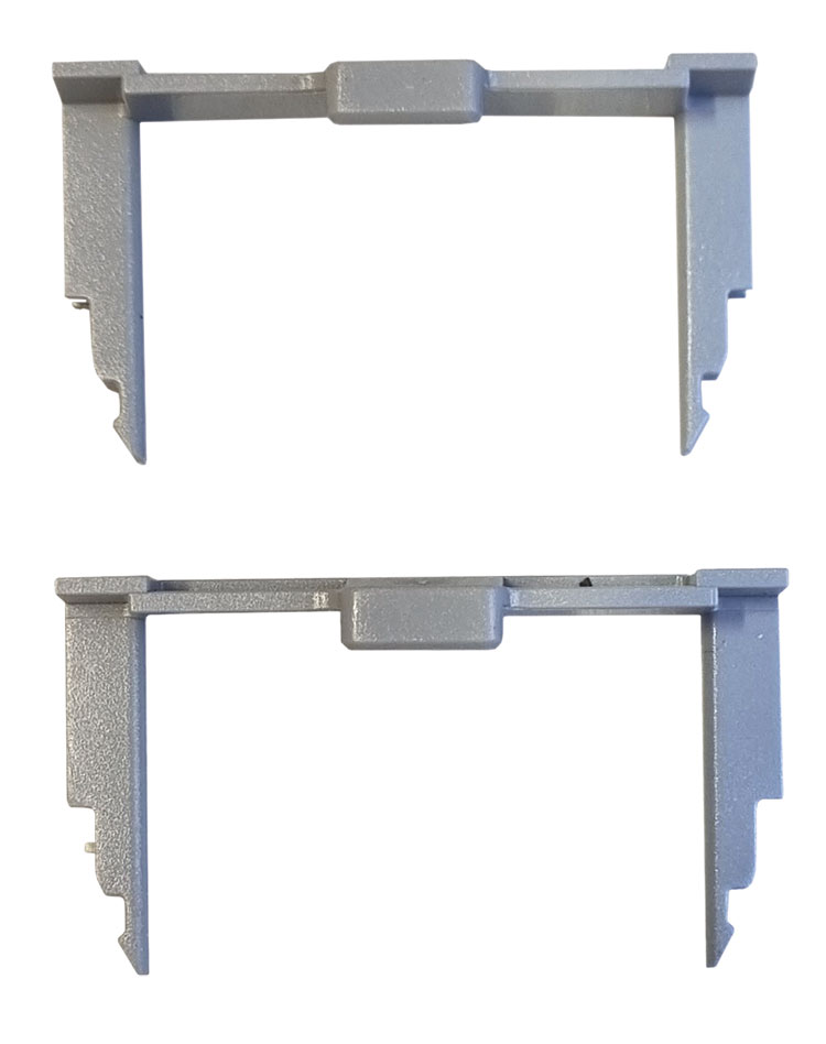
1x rear cover
2x 2x locking clip for shock and vibration applications
1x mounting frame
PM500D0400800F00:
1x empty module
1x Bus connector rear cover for PM-50 4.3" display
2x 2x locking clip for shock and vibration applications
1x mounting frame
Relay output (accessory):
PMM000I0RL200000:
2 x changeover contacts; switching capacity: 5 A at 250 VAC or 30 VDC; resistive load
PMM000I0RL400000:
4 x NO contacts;
Switching capacity: For one relay 3 A at 250 VAC or 30 VDC; resistive load
When using all relays switching capacity max. 1A/relay
Analog output (accessory):
PMM000I0AN000000:
0/4 mA to 20 mA or
0 VDC to 10 VDC
±10 VDC
Effec. Resolution: 16-Bit
RS232 interface (accessory)
PMM000CM23200000:
Possible baud rates: 300 to 115,200 bit/s
Data bits: 7 or 8
Parity: ungrade, grade or no parity
Ethernet interface (accessory):
PMM000CMENT00000:
10/100 T-Base
Auto MDI / MDI-X
RJ-45 socket
ModbusTCP communication possible.
AC supply (accessory):
PMM000PWACP00000:
Input: 85 VAC to 240 VAC; ±10%; 0.16 A to 0.3 A
Frequency: 50/60 Hz
Output: +15 VDC; ±10%; 0.8 A; max. 12 W
Insulation: 3 kV between primary and secondary side
Note:
The AC supply module must always be mounted in the last position of the communication flow.
Manufacturer:
Red Lion


Parameterize the PM-50 graphic display easily and conveniently via Android.
The app allows you to read, write, program and manage your PM50 display.
Parameterize the PM-50 graphic display easily and conveniently via iPhone or iPad.
The app allows you to read, write, program and manage your PM50 display.

RS232 interface module
RS232 interface module for the PM-50 base unit
Ethernet interface module
Ethernet interface module for the PM-50 base unit
Analog output module current/voltage
Analog output module for the PM-50 base unit
Relay output module 2x changeover contact
Relay output module for the PM-50 base unit
Relay output module 4x NO contact
Relay output module for the PM-50 base unit