Gould Modicon developed the first programmable logic controller. With the aim of enabling the controllers to communicate efficiently with each other via a serial bus system, they developed Modbus in 1979. It is now one of the oldest and most widely used standards. Modbus is easy and inexpensive to integrate into devices of all kinds. It can therefore be found in a large number of devices, such as sensors, counters, I/O modules, actuators, operating devices, displays, IPCs and in almost every control system.
Modbus TCP, which is based on Ethernet, was included as part of the IEC 61158 standard in 2007.

Modbus can be used via various transmission media:
Modbus Remote Terminal Unit (Modbus RTU) is the name given to transmission via the serial standards RS232, RS422 or RS485.
The possible baud rates range from 1,200 kBit/s to 115,200 kBit/s. Commonly used are 9600 kBit/s or 57,600 kBit/s, as the ratio of transmission rate to the permissible cable length is most balanced here. Bus terminating resistors must be set in accordance with the specifications of the RS485 transmission technology.
The connection technology used is 9-pin Sub-D plugs/sockets for RS232 or RS422/RS485, but screw terminals are also used for RS422/RS485.
For RS232, the pin assignment is standardized with pin 2 (receive line), pin 3 (transmit line) and pin 5 (ground). When wiring two RS232 devices, the receive line is connected to the transmit line of the other device. Prefabricated null modem cables are available for this purpose.
The serial Modbus transmission can also be transmitted from RS232/RS422/RS485 via other media (e.g. radio) and via the Internet using a media converter or modem. It must be ensured that the time behavior specified by Modbus (time between telegrams and time between individual characters of a transmission) is observed.
With ModbusTCP, the Modbus protocol is transmitted via Ethernet 10/100 BaseTx and the TCP layer. The data transmission rate is 10/100 Mbit/s. Transmission via WLAN, for example, is also possible without any problems.
Topology

Different topologies are used depending on the transmission medium used.
Modbus RTU with RS232 is a point-to-point connection. With RS422 and RS485, the structure follows a line structure which can be a multipoint connection (several participants). A network consists of ONE master and at least one slave. The master reads and writes individual slaves one after the other as required. An individual device address is used to identify the participants (valid range is 1 to 247).
All standard EtherNet topologies can be used with Modbus TCP. Modbus TCP refers to participants in the network that have either client (master) or server (slave) functionality.
The client is able to read and write to the server. The server makes data available or can be written to.
Modbus TCP Modbus RTU
Client -> Master
Server -> Slave
A device can also take on both roles. In contrast to Modbus RTU, there can be several clients (master) in a Modbus TCP network and a server (slave) can also serve several clients (the number of connections depends on the device).
Addressing takes place via the IP address. The Modbus device address within the Modbus telegram is 255, but most devices ignore this. This becomes relevant if the Modbus TCP server is a gateway from Modbus TCP to Modbus RTU(e.g. HD67507-xx) that works transparently. The Modbus device address can then be used to address a specific Modbus RTU device behind the Gateway.
The protocol usually uses TCP port 502 and can also be transmitted via routers to other sub-networks or via the Internet.
The Modbus protocol in general
The data model contains the following data types (from the perspective of a slave):
| Discrete input | Input bit | Read only |
| Coil | Output bit | Read and writeable |
| Input register | Input register (16 bit word) | Read only |
| Holding register | Output register (16 bit word) | Readable and writable |
If it is necessary to read or write larger amounts or types of data (e.g. 32- or 64-bit values), a corresponding number of bit or register values, starting from a start address, must simply be addressed with the appropriate command (function code) with the corresponding number of registers or bits in order to transmit the data consistently.
A maximum of 252 bytes can be transmitted within a Modbus telegram.
The so-called functioncodes(commands) are used to define the data direction (read or write) and the data type. The functional scope of the supported function codes varies from device to device.
The usual function codes include
| FC 01 | Read coils | Reading one or more bit outputs in sequence (reading back an output) |
| FC 02 | Read Discrete Inputs | Reading one or more bit inputs |
| FC 03 | Read Holding Register | Reading output registers in sequence (reading back an output) |
| FC 04 | Read Input Register | Reading input registers in sequence |
| FC 05 | Write Single Coil | Writing a bit output |
| FC 06 | Write Single Register | Writing a register output |
Further function codes can be | ||
| FC 15 | Write Multiple Coils | Writing several bit values in succession |
| FC 16 | Write Multiple Registers | Write multiple registers in sequence |
| FC 23 | Read/Write Multiple Registers | Writing and reading multiple registers in sequence |
Sometimes the supported function code is not specified in the documentation of a device. The information may then be based on the old memory organization of Schneider Electric controllers:
00001 0X bit types corresponding to the coils with data address 1
10001 1X bit types correspond to the input discrete with data address 1
30001 3X register types correspond to the holding registers with data address 1
40001 4X register types correspond to the input registers with data address 1
The management of the memory of a Modbus slave can be implemented differently, which often leads to errors in the addressing of the data.
In the first model, a slave has clearly separated memory areas for different data types. Each individual block is addressed via the corresponding read or write command (function code). The data is addressed via different start addresses with the desired offset. This prevents access to an unauthorized address range in combination with the function code provided for this purpose.

In the second model with a combined organized memory, the different data are always addressed via the same start address and corresponding offset. The same data can therefore be read or written bit by bit or register by register with the corresponding function code. Although this model is more flexible, it can happen more easily that due to an incorrect address offset or incorrect function code, the data that was actually required is not read. Data that has been read or written then appears nonsensical. For devices with this memory model, it is also possible that the function code (Read Registers) for reading inputs has not been implemented, so that the function code (Write Single Register or Write Multiple Registers) can be used to both read and write inputs.

A common error that is made during addressing is the different representation of the start address of a memory. For some devices, the start address is given in decimal form in the documentation, starting with 1. On others, the specification is made in hexadecimal, starting with 0x00. This often means that an offset of 1 is required when addressing data in order to read or write the desired data.
If the Modbus master addresses a slave with a function code not supported by the slave or an invalid data address, the slave responds with an error message (exception response).
| Exception code | Exception name | Exception Description |
|---|---|---|
| 01 | Illegal function | Modbus function code not supported |
| 02 | Illegal data address | Modbus data address invalid |
| 03 | Illegal value | Invalid data value in command (usually invalid write access) |

With Modbus RTU, the device address is usually set on each slave using DIP switches, rotary switches or software. To configure the master, the device addresses of the connected slaves as well as information about the supported function codes and the desired data addresses are required (can be found in the documentation for the slaves). The master is usually configured using its software.
For Modbus TCP, the respective IP address of the server and the port used (usually port 502) are also required. Server and client must be in the same network (same IP address range). The client is configured either via software or an integrated web server on the client.

Modbus ASCII, is actually just a modification of Modbus RTU in which the Modbus protocol is transmitted in the form of readable ASCII characters.
Very rarely encountered is ModbusPlus, which is also based on RS485 but works with the special ISO/IEC 3309:1991 HDLC standard on layer 2. It can be found in field devices and controllers from Schneider Electric. The difference to Modbus RTU is represented by two different data channels. On the one hand, the cyclic data (global data) and the acyclic data, which is requested from another participant in a similar way to Modbus RTU. The global data is sent by each participant on the bus whose turn it is according to the token passing procedure used. The data can then be read by any participant. The data transmission rate is 1 Mbit/s.
The Modbus Organization is a group of independent users and suppliers of automation devices that aims to promote the adoption of the Modbus communication protocol suite and the development of architectures for distributed automation systems in various market segments.
Areas of application
Mechanical engineering, building automation, home automation, measurement technology, etc.
Remote maintenance
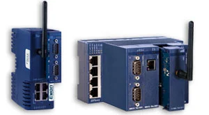
Modular remote maintenance and M2M router Ewon Flexy for remote maintenance and data services
IIoT platform
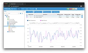
Collect & evaluate machine data centrally in the hardware-independent IIoT platform from VISUALYS. Easy connection of almost any Modbus TCP device.
Gateways
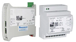
for connection to Modbus TCP interfaces
Server / Client.....
Various housing designs
Various bus protocols possible
Industrial Wireless
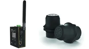
Machine connectivity via Bluetooth or WLAN reduces the amount of cabling required. The Wireless Bolt can work as an access point or as a client with WLAN and Bluetooth Central or Peripheral.
EtherNet/IO systems
Simple connection of analog (current, voltage or thermocouples) and digital sensors or contacts to ModbusTCP. The behavior of the inputs can be easily configured via software. Digital logic functions are programmable.
HMI and IIoT edge Gateways
Professional human-machine interface - Aesthetic design and ergonomic operation.
Gateways
for connection to Modbus RTU interfaces
Slave / Master .....
Various housing designs
Various bus protocols possible
Panel meters of the PAX series
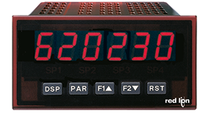
The PAX series panel meters (except PAXC and PAXR) can be equipped with the optional Modbus interface.
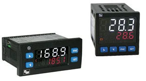
Universal controller Wachendorff
Equipped with a Modbus RTU Slave
interface via RS485
Sending and receiving data
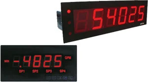
Large displays of the LPAX and EPAX series
The large displays of the LPAX series (except LPAXCXX and LPAXRXX ) and the EPAX series (except EPAXCXX and EPAXRXX ) can be equipped with the optional Modbus interface.
Products: LPAX series | Products: EPAX series |


