CANopen was developed in 1993 by the ASPIC research project and from 1994 by the CAN in Automation (CiA) user and manufacturer association.
As the name suggests, the communication protocol is based on CAN. CANopen defines the application layer and ensures significantly better cross-manufacturer interoperability through standardization. The data transmission functions of CAN are supplemented by CANopen with additional functions such as Redundancy, functional safety and support for complex network architectures. CANopen has been standardized as European standard EN 50325-4 since 2003. In addition, the CiA has published further recommendations for implementation in the form of CiA 303-1 (physical transmission) and CiA 301 and 302 application level.
Physics
The connection to the CANopen participants is made via a two-core twisted copper cable to the insert. Two additional wires for earth and a 5 V power supply are optional. This is a serial, half-duplex transmission technology.
The possible transmission speeds depend on the length of the data cable. The lower the data rate, the longer the possible cable length. For example, at a data rate of max. 1 Mbit/s up to 25 m is possible, at 125 kbit/s up to 500 m and at 10 kbit/s up to 5 km. Terminating resistors of 120 Ohm are required at the beginning and end of the bus line. Further possible physical transmission media are specified in ISO11898-2/3/5 and CiA303-1. Screw terminals, M8 and M12 screw connectors and Sub-D sockets/plugs are possible as further connection options.
Topology
As a classic fieldbus, CAN follows the line topology. Although spur lines or branches are possible, they should be avoided due to signal reflections. The length of the data line depends on the transmission rate used. CAN works with a producer / consumer system or broadcast system.
The data transmission rate is either detected automatically by the CAN participants or must be set manually on the device or via software.
This must be identical for all participants in the network.
Bus access takes place via arbitration, with each participant monitoring the bus at the start of the transmission. If another participant transmits at the same time, the dominant bit at the beginning of a message overwrites the recessive bit of the other participant. The sender of the overwritten message recognizes this and aborts the transmission in order to try again later.
The synchronization of all participants, e.g. for arbitration, begins when the first dominant or recessive bit is received. Synchronization is maintained by bit stuffing within the CAN message. After five bits of the same polarity, a bit with reverse polarity is inserted. The CAN transceivers of the receivers resolve this accordingly.
The priority on the bus is determined by the object identifier; the lower the identifier, the higher the priority. The messages are sent to the bus by the participants and all participants receive them.
the participants decide according to their configuration whether the message is also relevant for them according to their configuration or not.
There are two different standards for identifiers:
- The basic format uses 11-bit for message identification (CAN 2.0A)
- The extended format with 29-bit identifier length (CAN 2.0B)
The user data length within a message is 0-64 bits, i.e. up to a maximum of 8 bytes per message.
Up to 127 bus participants are permitted.
At the application layer, the master/slave model is also used for network management. The participants are usually started by NMT masters. The NMT messages are sent via the identifier 0, whereby the participants are set to different operating states with various commands.
At startup, the NMT master checks whether all subscribers are present and configures them via SDOs (Service Data Objects) if necessary. The SDOs can be used for both read and write access to a subscriber's object database. The client/server model is used for SDO communication, in which the client initiates the message and the server confirms the message. Depending on whether a client has been implemented in addition to the SDO server, communication between the participants is also possible via SDO.
Once the network has been started by the NMT master, the participants begin to transfer data via PDO (Process Data Object) (normal communication mode). The communication behavior of each object can be configured individually. Data is usually transmitted efficiently on an event-driven basis. One variant of the PDO is the timestamp.
With the help of sync messages, several PDOs can be transmitted synchronized. In the event of an error, devices can transmit emergency messages with an error code. Devices are monitored during operation using the optional heartbeat and node guarding functions. With Hearbeat, participants can monitor each other using SDO messages.
Application profiles have been defined by the CiA to further improve the range of functions and interoperability of CANopen devices. These define a minimum range of functions for a specific device type (e.g. for I/O modules, drives, sensors and controllers, encoders, etc.), particularly with regard to the object database.
Configuration
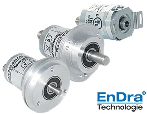
The baud rate (if not detected automatically) and the CAN identifier (device address) are usually configured. The manufacturer of a CANopen device provides an electronic data sheet (EDS file) that contains information on all CANopen device objects implemented in the device.
Further configuration is carried out using a CANopen configuration tool, which usually gains access to the bus either via the NMT master or via a PC to CAN adapter (e.g. USB to CAN adapter). The procedure is very rough: the first step is to integrate the EDS files of the connected devices. The connected network is searched for participants and the information from the EDS files is assigned according to the manufacturer and device IDs read out. The bus parameters are defined. The PDO mapping is then carried out, the transmit and receive process data objects (TxPDO, RxPDO) of the participants are assigned and the transmission parameters can be defined for each PDO. Once the configuration is complete, it is loaded to all devices via the bus (this is done using SDOs).
During commissioning, the configuration of a device using the EDS file defines parameter values, names etc. and generates a device configuration file (DCF file).

- CANopen FD (Flexible Data-Rate), user data length extended from eight to 64 bytes
- CANopen Safety offers functions for functional safety.
CAN in Automation (CiA)
International user and manufacturer group for the CAN network (Controller Area Network)
Areas of application
The CANopen is used in drive technology, robotics, medical technology, automotive, shipping, railroad technology,...
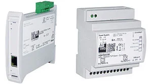
Gateways
Configurable Gateway for free data management
Galvanic 3-way isolation
Up to max. 1 Mbps CANopen data rate
Panel PC
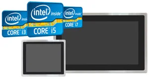
The ViTAM-9(A) series is based on a 4th or 6th generation Intel® Core™ processor. The panel PCs in this series are available in display sizes ranging from 15" to 24" and can be equipped with projected capacitive, resistive or no touch. These very powerful and efficient processor families provide sufficient computing power for medium and large applications and thus enable more extensive applications Industrial master, SCADA or IIoT monitor control applications.
To the products


